RPI Pico Analog Input
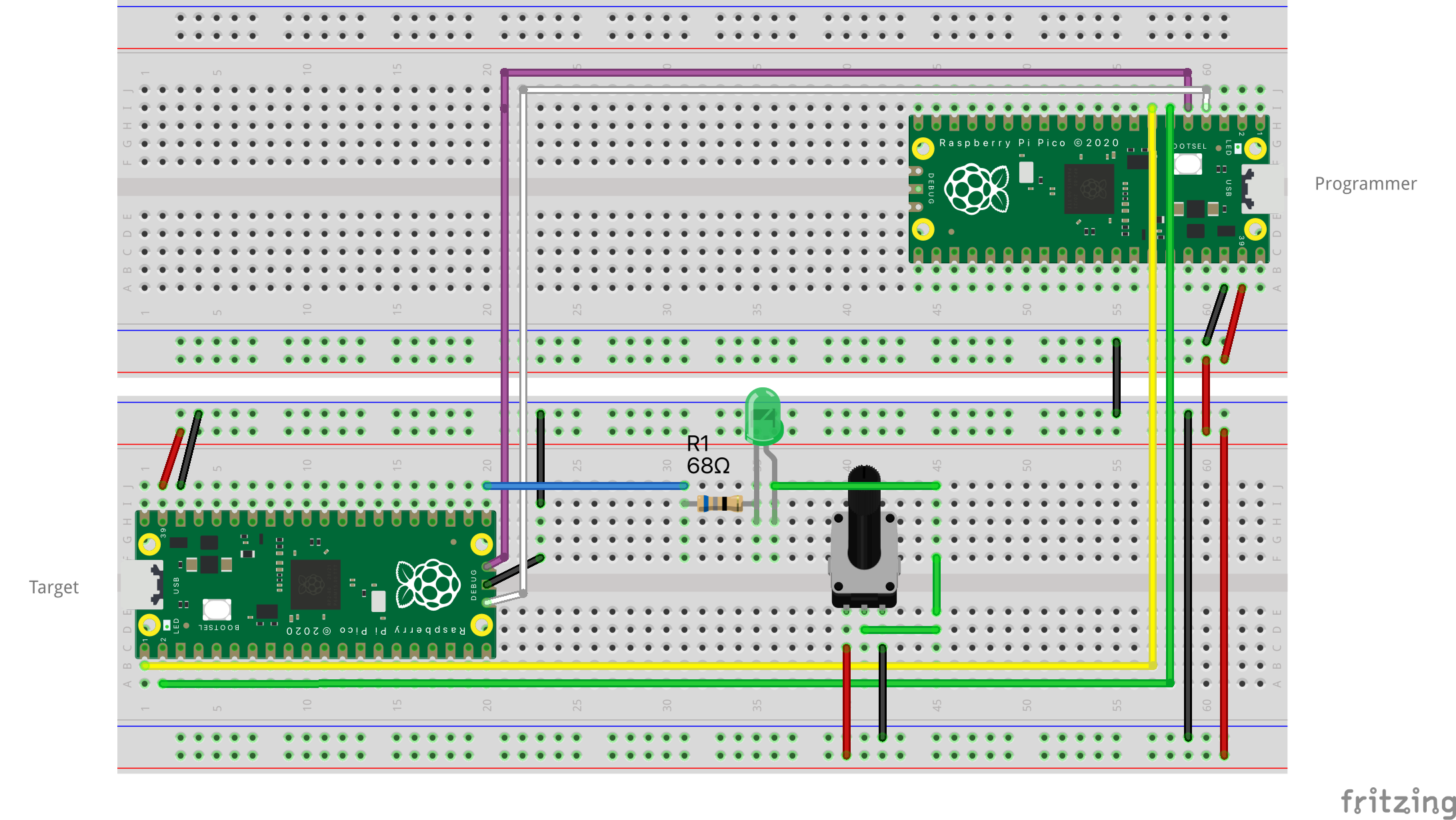
We'll continue to update our project and see if we can get some analog readings from a potentiometer. First, we'll update the breadboard to look like this:
Schematic:

If you have wired up the breadboard correctly, you should be able to control the brightness of the LED by turning the potentiometer.
Notice that we replaced the resistor for a 68Ω version. This is to compensate for the resistance of the potentiometer.
Reading analog input
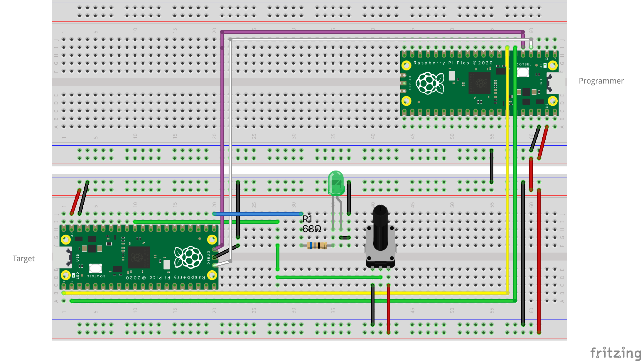
Ok, now that we have confirmed that the potentiometer is working, let's update the wiring one more time to connect the
potentiometer to the Pico board. Connect the middle pin of the potentiometer to pin GP26 on the Pico board, and the
other two pins to the 3V3 and GND pins.
Schematic:

Notice that we switched the connections of the potentiometer.
Update main.rs to look like this:
#![no_std]
#![no_main]

use defmt::*;
use embassy_executor::Spawner;
use embassy_rp::adc::{Adc, Async, Config, InterruptHandler};
use embassy_rp::gpio;
use embassy_rp::gpio::Pull;
use embassy_rp::{adc, bind_interrupts};
use embassy_sync::blocking_mutex::raw::ThreadModeRawMutex;
use embassy_sync::channel::{Channel, Sender};
use embassy_time::Timer;
use gpio::{Level, Output};
use {defmt_rtt as _, panic_probe as _};

bind_interrupts!(struct Irqs {
    ADC_IRQ_FIFO => InterruptHandler;
});

static CHANNEL: Channel<ThreadModeRawMutex, u16, 64> = Channel::new();

#[embassy_executor::main]
async fn main(spawner: Spawner) {
    let p = embassy_rp::init(Default::default());
    let mut led = Output::new(p.PIN_16, Level::Low);

    info!("Setting up ADC");
    let adc = Adc::new(p.ADC, Irqs, Config::default());
    let p26 = adc::Channel::new_pin(p.PIN_26, Pull::None);

    // spawn the task that reads the ADC value
    spawner
        .spawn(read_adc_value(adc, p26, CHANNEL.sender()))
        .unwrap();

    let rx_adv_value = CHANNEL.receiver();

    loop {
        let value = rx_adv_value.receive().await;
        // we should get a new value every 1s
        // the value we are getting will be somewhere between 0 and 4095

        info!("ADC value: {}", value);

        if value > 2048 {
            led.set_high();
        } else {
            led.set_low();
        }
    }
}

#[embassy_executor::task(pool_size = 2)]
async fn read_adc_value(
    mut adc: Adc<'static, Async>,
    mut p26: adc::Channel<'static>,
    tx_value: Sender<'static, ThreadModeRawMutex, u16, 64>,
) {
    let mut measurements = [0u16; 10];
    let mut pos = 0;

    loop {
        measurements[pos] = adc.read(&mut p26).await.unwrap();
        pos = (pos + 1) % 10;

        if pos == 0 {
            // compute average of measurements
            let average = measurements.iter().sum::<u16>() / 10;

            // send average to main thread
            tx_value.send(average).await;
        }

        Timer::after_millis(100).await;
    }
}
The code above is a bit more complex than the previous examples. We are now using the ADC peripheral to read the value
from the potentiometer. The read_adc_value task reads the value from the ADC every 100ms and computes the average of
10 measurements. The average is then sent to the main task that will control the LED.
We'll use channels, similar to tokio channels, to communicate between the tasks. The Channel is a simple
implementation of a channel that uses a Sender and a Receiver to send and receive messages between tasks.
Whenever there is a new value from the ADC, the main task will check if the value is greater than 2048. If it is, the LED will be turned off, otherwise it will be turned on. In practice, this means that if the potentiometer is turned to the right, the LED will be turned on, and if it is turned to the left, the LED will be turned off.
Run the project with:
$ cargo run --release